# System Architecture
In Progress
This chapter is incomplete - still being written/defined.
# Definitions and Topologies
This is a standard about microgrids. For the purposes of this standard, a microgrid can be defined as a network of interconnected devices that consume power, source power or both where the devices operate under a single administrative control that manages how power is moved and allocated to devices. Microgrids have the capability of operating without a connection to a national AC grid though they may be connected to the AC grid intermittently or even permanently.
Devices in the microgrid are connected with wired links. The point of connection between a device and the external wiring of the grid is referred to as a grid port. A grid port can source power, consume power or both. Links can be point-to-point as a direct wire between one port on each device:

Links can also be bussed, meaning that multiple ports can be attached to a common backbone such as a distribution cable or bus bar:

A device can have multiple grid ports permitting the device to participate in multiple links.
Devices with multiple ports permit the microgrid to have various configurations such as a series of point to point links, sometimes referred to as a "daisy chain":

In this example, the 48V link and the 12V link connect standard conforming ports while the connections between the solar array to the power source, and the battery to the DC-DC converter are not standard conforming. The devices convert the non-conforming ports to conforming ports.
Or an arbitrary combination of links forming a mesh that may contain loops:
# Hierarchical Grids
The term device in the preceding section should be interpreted loosely to be any collection of electronics. To the standard, a device is a single entity with a unique communications address that participates in the power allocation under that identity. Note that the device may incorporate another standard conforming microgrid within itself to perform its function. For example, a solar home system (SHS) may include a solar panel, battery subsystem and appliances operating in a bussed grid conforming to this standard.
Need picture
Solar home system picture
A neighborhood of such solar home systems may form another standard conforming microgrid operating as a grid of grids.
Need picture
Connected neighborhood pictures.
Extending the model further, neighborhoods may be combined into another microgrid as grid of grid of grids and so on.
Need picture
Grid of grid picture.
It is this arbitrary depth of hierarchy that causes this standard to refrain from using other terms that are sometimes used to refer to particular positions in the hierarchy such as nanogrid, picogrid etc.
# Link Properties
The properties of a link include its range of permitted voltages and currents and a communications technology associated with the link. This standard defines multiple types of links as subsections of the standard. A device conforms to the standard if it has at least on grid port that conforms to one of the types of links defined in the standard. It may have other electrical ports that do not conform to any of the standard links.
The DC grid allows to interconnect multiple energy sources and sinks.
Compared to conventional grids, where the energy flow is mostly uni-directional from the energy source to the consumer, the meshed DC grid can operate in both directions. A battery for example can be a current source or a current sink.
In order to explain the grid topology, the overall system is divided into abstract sub-components, as described below. These components don't necessarily need to be separate physical devices, but can be different sub-components in one circuit.
# Power line
Bipolar connection (cable) between exactly two grid ports. Splices are not allowed.
A power line might cover long distances, resulting in a voltage drop caused by the resistance of the cable. The voltage drop has to be considered to allow stable system control.
# DC bus
Connection of two or more electrical circuits such that the electric potential at each connection point can be considered equal. This can be achieved either by connecting each participant very close to each other or by using large copper cross-section such that voltage drop introduced by current flow is negligible.
The cross section of the conductor must be large enough to handle the sum of the maximum current of all connected sources.
# DC grid port
Connection between a DC bus and a power line, featuring
- a circuit breaker or electronic switch to allow disconnection of the port for safety reasons or to optimize energy flows and
- measurement of port current and bus voltage.
# Voltage converter
A DC/DC converter, necessary to connect DC buses of different voltage levels, e.g. a battery or solar panel to the DC grid.
# System overview
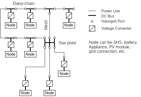
The following image gives an example of a possible DC grid layout.
It consists of a daisy-chained bus topology at the left side, a star point in the middle and includes a loop. The overall topology is called a mesh, as it allows redundant current paths.
Above schematic diagram assumes two different types of node connections to the grid. One type includes two DC grid ports, i.e. allows daisy-chaining of nodes. The other nodes at the bottom have only one DC grid port and need to be connected to a current router (star-point).
# Functional States
A functional state defines a mode of operation for a device attached to the grid. People often think of devices as either on or off, with on meaning that a device performs alls its normal functions and off meaning that the device has no response. In practice, many devices have more complex behaviors, particularly those with batteries. Even more complex behavior can occur when a device can be attached to a power source that varies over a range of voltages. To harmonize with ISO 21780, this standard defines several functional states based on more fundamental concepts of operational derating, switch-off, and damage.
Operational derating means failing to perform normal, expected behavior. This can be functional in the sense that some of the devices normal functions are not available. For example, a device may display indicator lights and respond to button presses but may be unable to perform its normal function such as a refrigerator that cannot operator its compressor to cool its contents. Operational derating can also be performance related such as a pump that cannot create its normal pressure but can still create some pressure.
Switch-off corresponds to the familiar concept of off in the sense that the device has minimal or no functionality and consumes minimal power. A device that is switched off may still consume enough power to enable it to be turned on with a message or button press.
Damage means that a device may not perform normally even when full power is available. The standard further distinguishes between fire-safe damage and unlimited damage potentially even include a fire. For example, consider a device with fuse-based over-voltage protection. When subjected to over voltage, the fuse may open and need to be replaced before the device can resume normal operation. Even so, the device has no risk of catching fire. Unlimited damage, such as when a device has experienced a full lightning strike means that its behavior is unspecified and it may, in fact, catch fire.
This standard defines the following functional states (harmonized with ISO 21780):
- FS1 - Normal operation with no derating or switch-off.
- FS2 - Device specified derating permitted but no switch-off. The device does not have enough power to operate normally but its control interface is operational.
- FS3 - Device specified derating permitted including switch-off or complete non-operation but no damage. The device will return to FS1 when appropriate power is restored.
- FS4 - Not used in this standard. ISO 21780 defines this as requiring a vehicle status change such as restart.
- FS5 - Derating and fire-safe damage may occur. A device is this state may not operate again but it will not catch fire.